
So many readers have asked me about “Stepped Hulls” and with this in mind, I thought it might be a good idea to write a brief article about this concept and design feature on the hull bottom of a planing hull.
Stepped bottoms have been used for a very long time to improve performance. A very famous design was Maple Leaf, built of wood in 1912, and since then many successful racing hulls have had this type of bottom. One can say that it is a further refinement of the deep V-Hull…
What is a step?
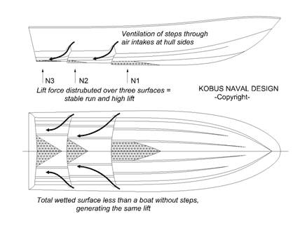
Steps are breaks in the hull intended to reduce the amount of hull surface in contact with the water. Steps can run straight across the hull (although these are structurally weak and not often seen today), or they can be V-shaped, with the vertex facing forward or aft. They will have large apertures on the outboard side of the hull to allow air to be sucked down into and ventilate the step. In general, a speed increase of about 10 to 15 percent can be expected from a stepped hull over a non-stepped hull with the same power train.
The reason why the stepped hulls are more effective is that the wetted area is divided into several smaller areas each with a large beam compared to the length;
Short, wide (high-aspect) surfaces are more efficient than long, narrow (low-aspect) ones in terms of frictional drag on water. Lift generation is just far more efficient with a large beam-to-length ratio surface. So, the idea behind a stepped bottom is to reduce wetted surfaces by allowing the hull to plane on two or three high-aspect planning surfaces rather than one large, low-aspect surface.
And the popular notion that any added speed from a stepped bottom is due to a layer of bubbles undoubtedly reduces frictional drag to some extent, but the real saving is in minimizing the hull area in contact with the water, specifically by presenting two or three wide and short surfaces to the water instead of one long, narrow one.
How its works!
As I have explained in a previous article on hull shapes, lift production is more efficient for a surface, with a small length-to-beam ratio. (The planning bottom is different from a wing, where it usually does not help split the surface into several tandem wings.) The increased lift generation capability means that the total wetted surface may be reduced, as well as the friction. My drawing shows that the region behind each step has to be ventilated. The air thus has to be sucked into this region in sufficient quantities. Normally this is not a problem since the pressure is very low, but it’s extremely important that the air supply is not cut. New air is continuously needed since the water entrains the air behind each step. This may be achieved most simply by extending the step sideways to the open air at the hull’s side.
When does it start to work?
In general, data indicate that if a boat can’t cruise easily at close to 30 knots or more, it can’t go fast enough to ride up on hull steps, so steps would only add drag. More specifically, this means that a petrol-powered family cruiser with steps should be able to cruise fully loaded at 30 knots, not just reach this speed at full throttle. Otherwise, the extra cost of tooling and the added time and cost spent laying up a stepped hull is wasted, and the stepped bottom is just a marketing gimmick. Some runabout builders even carve out a little scoop at the chime amidships, which I suppose is meant to suggest that the bottom is stepped, when in fact the bottom is as straight as an arrow.
The downside to the step hull
This principle is somewhat dangerous.
since the openings may be closed temporarily (and momentarily) by waves. When the air supply is lost, a backflow occurs behind the step causing an excessive increase in resistance. The speed thus drops momentarily – a dangerous situation, which may even cause injuries to the crew. If the supply is cut only on one side the hull will turn abruptly, and possibly even capsize. To avoid this problem air is often sucked through openings well above the waterline, or it may be supplied through tubes from deck level. Another possibility is to discharge the exhaust gases through the step. In this way the gases will be sucked out, improving the efficiency of the engine.
Builders often provide large inlets to the areas behind the steps, and a few even provide air paths through ducts that lead to the trailing vertical edge of the steps.
Since the lift is now spread to several surfaces along the hull (see drawing) the longitudinal stability becomes very large. It is difficult to change the trim. This is no problem in smooth water, but in a seaway, the hull may tend to follow the contour of the waves. Larger hulls may acquire a tendency to bump into the next wave, making the ride very uncomfortable. Smaller boats, which tend to jump between waves, are not so affected by this problem. Another effect of spreading the lift to several efficient surfaces, one after the other, is that the transverse stability may be put into jeopardy. The hull rides high on a very narrow set of wetted surfaces. At very high speed some designers have chosen to take advantage of the aerodynamics of the above-water part of the hull, using wing-like devices to keep the hull upright. Transom flaps may be fitted to the hull to control the trim. Temporary adjustments for correcting changes in the center of gravity may thus be made easily. The flaps may also be used to adjust the trim when the hull is running at off-design speeds, for instance in restricted waters or when the hull is under acceleration. This reduces fuel consumption and, even more importantly, the generated waves, which may be excessive at these speeds. It is also possible to use the flaps for adjusting the trim in a seaway to reduce the bumpiness.
My conclusion
Stepped hulls should be used by experienced drivers who know what the hull is likely to do in a seaway and in hard cornering, and who know how to react to the unexpected.